RA110 Spreader Beam
The spreader beam is designed for lifting and transporting equipment and cargo weighing up to 110t. It is adjustable every 1ft within the range of L=6ft to L=46ft, as specified in the manual. The spreader beam is intended to work solely in conjunction with lifting units equipped with appropriate chain or line slings.
Specification
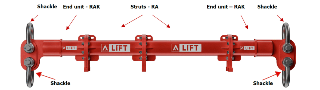
Spreader Beam RA110 WLLmax=110t, Lmax=46ft consists of:
- 2 end units RAK: 3ft
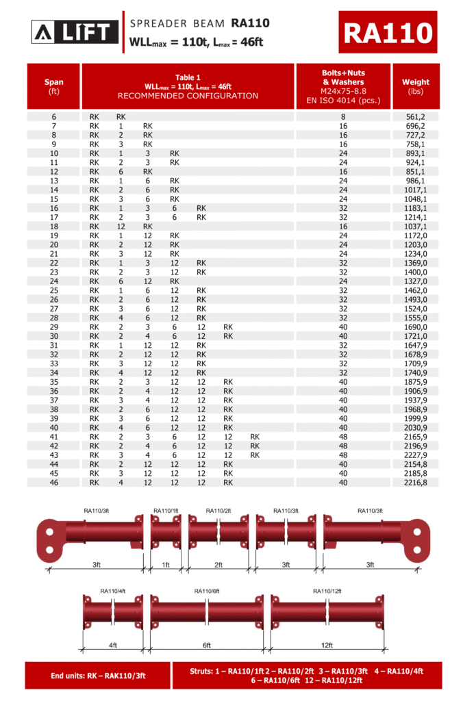
- Struts RA used to adjust the span: 1ft, 2ft, 3ft, 4ft, 6ft, 12ft
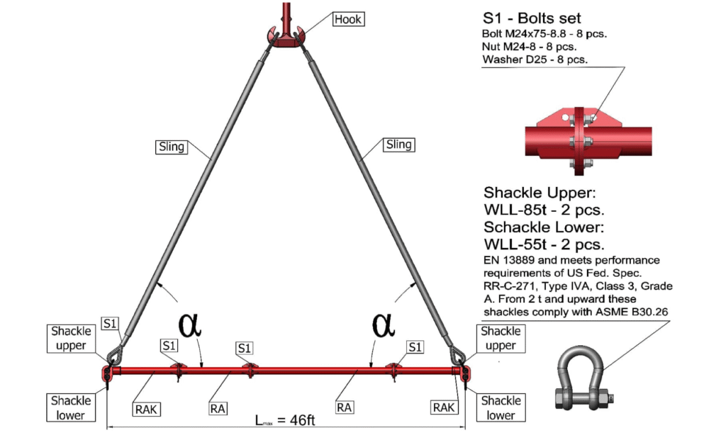
- 2 shackles WLL=55t and 2 shackles WLL=85t
- Maximum weight of the spreader beam, according to the recommended configuration, is 2216,8 lbs
- Carrying capacity from 15t to 110t
- The α angle between the beam and sling is 45° or more
- Use a bolt set to tighten (bolt+washer+nut) class 8.8. as per EN ISO 4014
- Bolt tightening torque 260 Pound-Foot. Spanner size required 36mm
- Torque wrench and ring spanner are recommended as additional equipment
Notice
- The guidelines outlined in ASME B30.20 – 2021 must be followed when using the A-LIFT equipment.
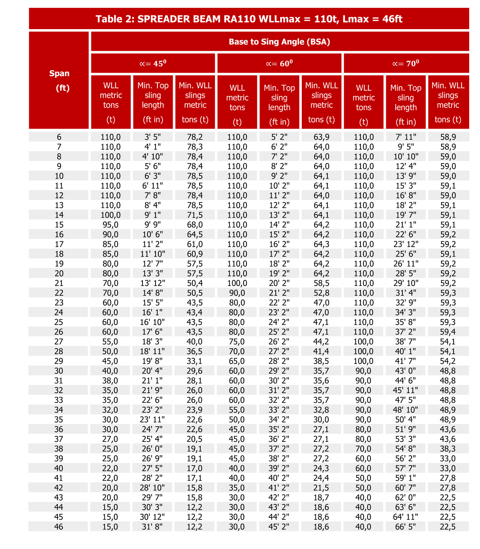
- Never exceed the indicated WLL; adhere to the WLL values listed in Table 2 for the specific sling angle used.
- To ensure the safe use of the spreader beam, the top sling length is essential – refer to Table 2.
- Under no circumstances should a load be suspended from the tube or flanges, as the spreader is designed for axial
compression and not intended for bending. - Shackles are not a part of the spreader beam. They are an additional option selected as per customer’s needs.
COMMON RIGGING MISTAKES
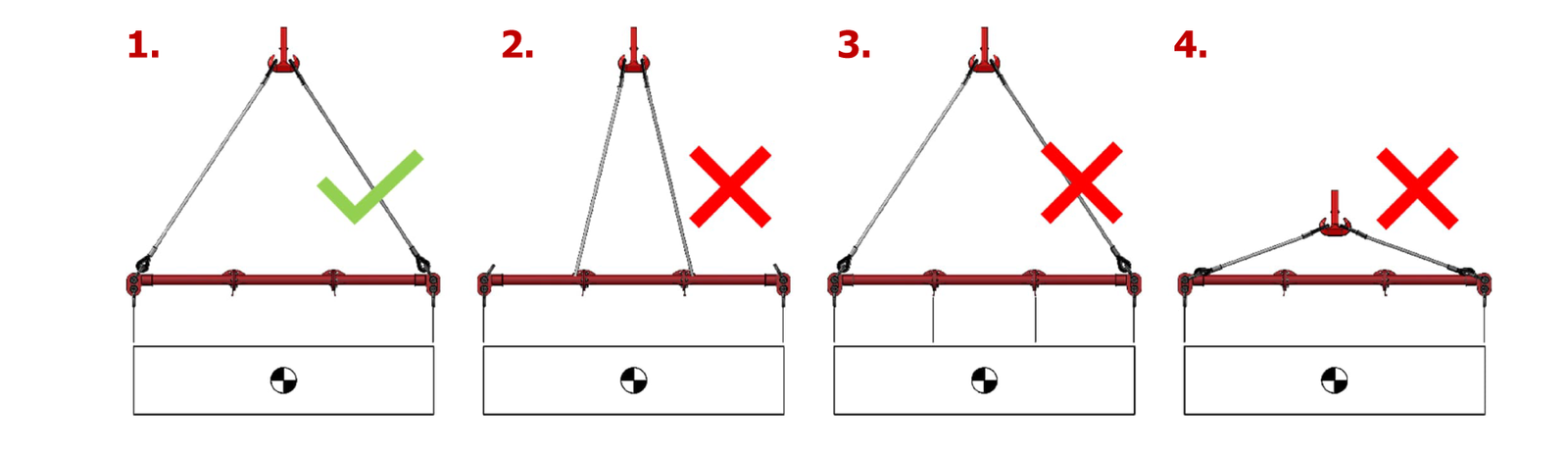
- Correct sling set up example.
- Incorrect. Upper slings are not attached to the end units.
- Incorrect. The second pair of slings below cannot be attached to the spreader beams.
- Incorrect. Sling angle α cannot be less than 45°
Assembly Method
- Verify the size of each A-LIFT component by checking its tag ID to ensure the correct size is being used.
- Arrange the beam elements on a flat surface according to Table 1 to prevent rolling.
- Before connecting, make sure that all elements and fasteners are free of any debris.
- Assemble the components using the provided bolts, nuts, and washers. Tighten bolts to the torque values specified.
- To ensure the safe use of the spreader, especially for longer spans, the quantity and quality of bolts are crucial.
- Put the jaw of the top shackle over the jaw of the end unit and attach a top sling to the top shackle’s body.
- Repeat the process for the other end of the spreader beam after inserting the top shackle pin through the shackle
and the end unit jaw. - Attach the crane hook to the free ends of the top slings.
- Attach lower slings and shackles to the lower holes of the end caps, and then connect them to the load to be lifted.
- Prior to lifting, a competent person must conduct a comprehensive inspection of the assembled spreader beam and lifting rig.
Attention!
- Ensure that the beam is loaded exclusively through the RAK end units only.
- Ensure the use of the correct top slings and avoid needless twisting of any slings.
- Keep obstacles away from the loaded spreader, as any contact could result in beam failure.
- Do not exceed the specified WLL for a particular span. Refer to Table 2.
- Avoid hanging any loads from the spreader tube, flanges, or support stands.
- Use tag lines to control movement when moving or positioning long elements or assemblies.
- Individual components might be heavy; therefore, exercise utmost caution when manual handling is necessary.